
What is Monitor
Definition of Monitor
A monitor is a type of external hardware that is used to display visual information generated by a computer. It is an output device that allows users to view images, text, videos, and graphics produced by the computer’s central processing unit (CPU) and graphics card.
Monitors typically consist of a visual display, circuitry, casing, and a power supply. The display itself is usually a thin and flat screen that utilizes various technologies such as liquid crystal display (LCD) or light-emitting diode (LED) to produce the visual output. The casing holds all the components together and often includes buttons or controls to adjust screen settings.
One common type of monitor connection is High Definition Multimedia Interface (HDMI), which enables the transmission of high-quality audio and video streams between the computer and the monitor. Other connection options include Display Port, VGA, and DVI.
Monitors are an essential component of a computer system, allowing users to interact with the computer’s user interface, desktop, and open programs. They provide a visual representation of the data and information processed by the computer, making them crucial for tasks such as web browsing, content creation, gaming, and multimedia consumption.
In summary, a monitor is an external hardware device that displays visual information generated by a computer. It is a vital component of a computer system, enabling users to view and interact with the output produced by the computer’s CPU and graphics card.
History of Monitors
The history of monitors begins with the invention of the cathode-ray tube (CRT) in 1897 by German physicist Karl Ferdinand Braun. The CRT was a significant development in display technology and became the foundation for early electronic displays. It consisted of a cathode tube with a fluorescent screen that produced images when an electron beam struck the screen.
The CRT technology was commercialized in 1922, and these early monitors were used primarily for data processing. However, television sets were used as computer monitors from the late 1970s to the early 1980s. This repurposing of TV sets allowed for the development of hardware and code to connect computers to these displays.
In the 1950s, CRT displays started appearing in computers, adapted from radar and oscilloscope CRTs. These early CRT monitors were primitive but marked an important milestone in the evolution of computer displays.
In the 1960s, the discovery of electroluminescence led to the development of flat panel displays. However, these displays were initially too costly, and CRT monitors continued to dominate the market.
It wasn’t until the 1990s that LCD screens became more affordable and started to replace CRT monitors. LCD (liquid crystal display) technology offered several advantages over CRT, including smaller size, lighter weight, and lower power consumption.
The history of monitors is closely tied to the development of computer hardware assets. As computers evolved, so did the need for better display technology. Monitors are an essential component of computer systems, allowing users to interact with the digital world and visualize data. The advancements in display technology have played a crucial role in improving user experience, productivity, and the overall functionality of computer systems.
Overall, the history of monitors showcases the progression from bulky and heavy CRT displays to sleek and energy-efficient flat panel displays. This evolution has significantly impacted the design and usability of computer systems, making them more compact, portable, and visually appealing.
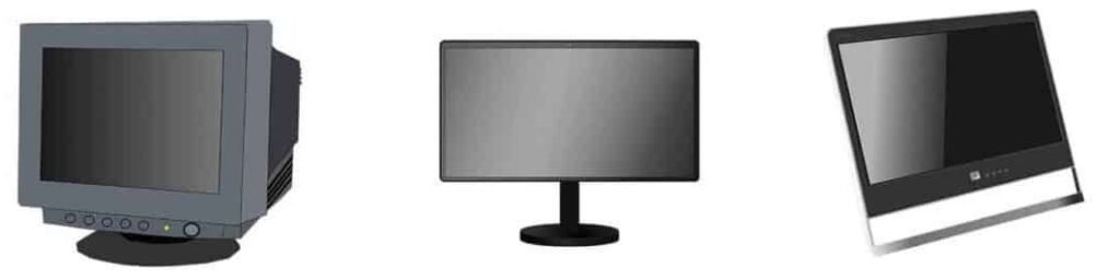
Types of Monitor
CATHODE RAY TUBE (CRT) DISPLAY
The device which allows, the amplitude of such signals, to be displayed primarily as a function of time, is called cathode ray oscilloscope. The cathode ray tube (CRT) is the heart of the C.R.O. The CRT generates the electron beam, accelerates the beam, deflects the beam and also has a screen where beam becomes visible as a spot. The main parts of the CRT are
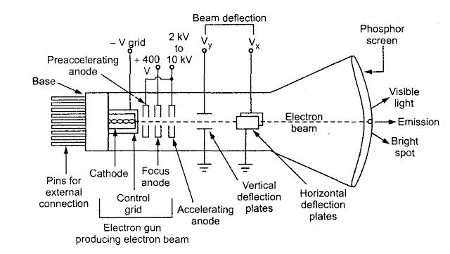
- Electron gun
- Deflection system
- Fluorescent screen
- Glass tube or envelope
- Base
Electron Gun
- The electron gun section of the cathode ray tube provides a sharply focused, electron beam directed towards the fluorescent-coated screen.
- This section starts from thermally heated cathode, emitting the electrons.
- The control grid is given negative potential with respect to cathode.
- This grid controls the number of electrons in t beam, going to the screen.
- The momentum of the electrons (their number x their speed) determines the intensity, or brightness, of the light emitted from the fluorescent screen due to the electron bombardment.
- The light emitted is usually of the green colour.
Deflection System
- When the electron beam is accelerated it passes through the deflection system,
- with which beam can be positioned anywhere on the screen.
Fluorescent Screen
- The light produced by the screen does not disappear immediately when bombardment by electrons ceases, i.e., when the signal becomes zero.
- The time period for which the trace remains on the screen after the signal becomes zero is known as “persistence or fluorescence”.
- The persistence may be as short as a few microseconds, or as long as tens of seconds or even minutes.
- Medium persistence traces are mostly used for general purpose applications.
- Long persistence traces are used in the study of transients.
- Long persistence helps in the study of transients since the trace is still seen on the screen after the transient has disappeared.
Glass Tube
- All the components of a CRT are enclosed in an evacuated glass tube called envelope.
- This allows the emitted electrons to move about freely from one end of the tube to the other end.
Base
- The base is provided to the CRT through which the connections are made to the various parts.
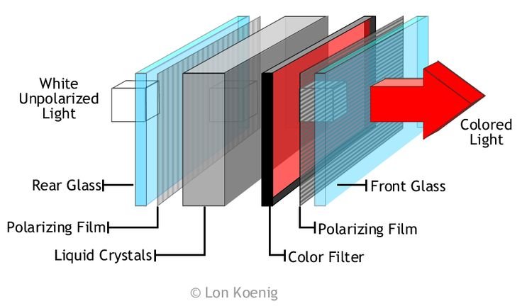
Liquid Crystal Display (LCD)
A liquid crystal display (LCD) is a thin, flat panel used for electronically displaying information such as text, images, and moving pictures. Its uses include monitors for computers, televisions, instrument panels, and other devices ranging from aircraft cockpit displays, to every-day consumer devices. It is an electronically-modulated optical device made up of any number of pixels filled with liquid crystals and arrayed in front of a light source (backlight) or reflector to produce images in color or monochrome.
LCD major features are:
- Its lightweight construction,
- Its portability,
- Its ability to be produced in much larger screen sizes.
- Its low electrical power consumption enables it to be used in embedded systems.
Each pixel of an LCD typically consists of a layer of molecules aligned between two transparent electrodes, and two polarizing filters, the axes of transmission of which are (in most of the cases) perpendicular to each other. With no actual liquid crystal between the polarizing filters, light passing through the first filter would be blocked by the second (crossed) polarizer.
LCD Specifications:
Important factors to consider when evaluating an LCD monitor:
- Resolution: The horizontal and vertical screen size expressed in pixels (e.g., 1,024×768).
- Dot pitch: The distance between the centers of two adjacent pixels. The smaller the dot pitch size, the less granularity is present, resulting in a sharper image. Dot pitch may be the same both vertically and horizontally, or different (less common).
- Viewable size: The size of an LCD panel measured on the diagonal (more specifically known as active display area).
- Response time: The minimum time necessary to change a pixel’s color or brightness. Response time is also divided into rise and fall time. For LCD monitors, this is measured in btb (black to black) or gtg (gray to gray).
- Input lag : a delay between the moment monitor receives the image over display link and the moment the image is displayed. Input lag is caused by internal digital processing such as image scaling, noise reduction and details enhancement, as well as advanced techniques like frame interpolation. Input lag can measure as high as 3-4 frames (in excess of 67 ms for a 60p/60i signal). Some monitors and TV sets feature a special “gaming mode” which disables most internal processing and sets the display to its native resolution.
- Refresh rate: The number of times per second in which the monitor draws the data it is being given.
- Matrix type: Active TFT or Passive.
- Viewing angle: (coll., more specifically known as viewing direction).
- Color support: How many types of colors are supported (coll., more specifically known as color gamut).
- Brightness: The amount of light emitted from the display (coll., more specifically known as luminance).
- Contrast ratio: The ratio of the intensity of the brightest bright to the darkest dark.
- Aspect ratio: The ratio of the width to the height (for example, 4:3, 5:4, 16:9 or 16:10).
- Input ports (e.g., DVI, VGA, LVDS, Display Port, or even S-Video and HDMI).
Light Emitting Diode (LED)
- The Light emitting diode is a two-lead semiconductor light source.
- In 1962, Nick Holonyak has come up with an idea of light emitting diode, and he was working for the general electric company.
- The LED is a special type of diode and they have similar electrical characteristics of a PN junction diode. Hence the LED allows the flow of current in the forward direction and blocks the current in the reverse direction.
- The LED occupies the small area which is less than the 1 mm2. The applications of LEDs used to make various electrical and electronic projects.
- The light emitting diode is a p-n junction diode. It is a specially doped diode and made up of a special type of semiconductors. When the light emits in the forward biased, then it is called as a light emitting diode.
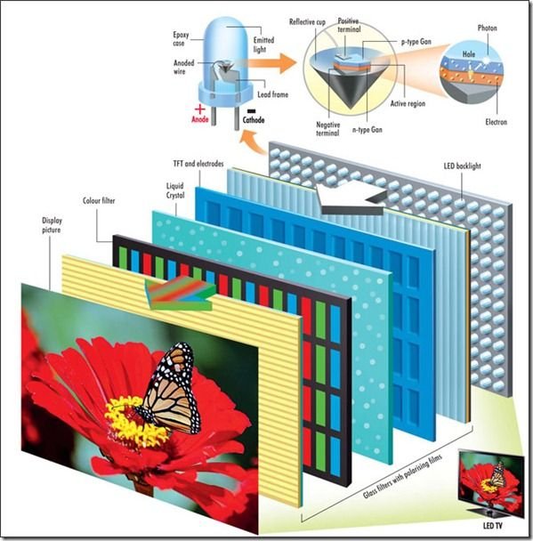
How does the LED work?
- The light emitting diode simply, we know as a diode.
- When the diode is forward biased, then the electrons & holes are moving fast across the junction and they are combining constantly, removing one another out.
- Soon after the electrons are moving from the n-type to the p-type silicon, it combines with the holes, and then it disappears.
- Hence it makes the complete atom & more stable and it gives the little burst of energy in the form of a tiny packet or photon of light.
- From the diagram, we can observe that the N-type silicon is in red color and it contains the electrons, they are indicated by the black circles.
- The P- type silicon is in the blue color and it contains holes, they are indicated by the white circles.
- The power supply across the p-n junction makes the diode forward biased and pushing the electrons from n-type to p-type. Pushing the holes in the opposite direction.
- Electron and holes at the junction are combined.
- The photons are given off as the electrons and holes are recombined.
Types of LED
- Gallium Arsenide (GaAs) – infra-red
- Gallium Arsenide Phosphide (GaAsP) – red to infra-red, orange
- Aluminium Gallium Arsenide Phosphide (AlGaAsP) – high-brightness red, orange-red, orange, and yellow
- Gallium Phosphide (GaP) – red, yellow and green
- Aluminium Gallium Phosphide (AlGaP) – green
- Gallium Nitride (GaN) – green, emerald green
- Gallium Indium Nitride (GaInN) – near ultraviolet, bluish-green and blue
- Silicon Carbide (SiC) – blue as a substrate
- Zinc Selenide (ZnSe) – blue
- Aluminium Gallium Nitride (AlGaN) – ultraviolet